
Can stacking thousands of tiny, noisy spectral lines really reveal an Earth‑like planet? Cross‑correlation does just that by turning weak, scattered line shifts into one measurable velocity signal. The technique uses template matching and Doppler shift analysis (Doppler shift: how wavelengths change when something moves). You slide a reference spectrum across the data and the best match shows the star’s radial velocity as a sharp peak. In this post we’ll walk through the CCF math, template and mask choices, instrument and calibration needs, key noise sources, and practical tips for reaching meter‑per‑second precision.
Core Principles of the Cross‑Correlation Function (CCF)

The cross‑correlation function measures how well an observed stellar spectrum matches a reference template when you slide one past the other at different velocity offsets. When a planet pulls its host star toward or away from us, the star’s whole spectrum shifts in wavelength. Blueward if it’s coming closer, redward if it’s moving away. That shift follows Δλ/λ = v/c, the standard Doppler formula. Instead of watching just one spectral line, cross‑correlation compares thousands at once, sliding the template across a grid of trial velocities until it finds the best fit. The velocity offset that gives the strongest correlation is the star’s radial velocity at that instant.
Why does this matter? Any single absorption line is narrow, often blended with neighbors or buried in noise. By lining up the Doppler shifts from hundreds or thousands of lines into one composite profile (the CCF), you turn a bunch of weak signals into a single sharp peak. That boost in signal‑to‑noise is what lets astronomers spot velocity wobbles as tiny as one meter per second or less, the precision you need to catch Earth‑mass planets in habitable‑zone orbits.
The CCF sits at the heart of radial‑velocity planet hunting because it’s both fast and reliable. You don’t need to model every detail of a star’s atmosphere. You just lean on the fact that the entire forest of spectral lines shifts together when the star moves. Here’s why the CCF is essential:
Noise suppression: Stacking many lines averages out random photon noise, cosmic‑ray hits, and pixel glitches that mess up individual lines.
Speed: Cross‑correlation runs quickly, especially when you use fast Fourier transforms, so you can reduce dozens of spectra each night.
Flexibility: One good template or line mask works across different spectral types and observing conditions.
Direct readout: The CCF peak position gives you radial velocity straight away. No need for complicated iterative fits in the first pass.
Methods for Constructing Cross‑Correlation Profiles
Building a CCF starts with picking a reference that captures the line pattern you expect in the star’s spectrum. Two common picks are a high signal‑to‑noise spectrum of a similar star (the template spectrum) or a numerical line mask that lists wavelength positions and weights of clean absorption lines. Synthetic spectra from stellar atmosphere models do the same job. The idea is to have a blueprint showing where deep, unblended lines sit so you can line up each observed spectrum against it.
Before you correlate anything, the observed spectrum gets preprocessed. Echelle spectrographs split starlight into dozens of diffraction orders. Each order is extracted, flat‑fielded to remove pixel variations, and normalized by dividing out the blaze function and continuum. Cosmic rays get clipped, and stretches dominated by telluric water or oxygen bands are masked. If your template is an observed spectrum, it goes through the same steps. Resampling both onto a uniform logarithmic wavelength grid is critical, because a constant step in ln(λ) equals a constant velocity step. That linearizes the Doppler shift and turns correlation into a simple shift‑and‑multiply operation.
The correlation itself runs in five steps:
- Load preprocessed spectrum and template (or mask) onto matching logarithmic‑wavelength grids.
- Shift the template by trial velocity steps, usually from −100 km/s to +100 km/s in increments of hundreds of m/s or finer.
- Multiply the observed spectrum by the shifted template pixel by pixel and sum the products. That sum is the CCF value at that trial velocity.
- Repeat for all trial velocities to build the full CCF curve.
- Combine orders by computing per‑order CCFs and adding them with inverse‑variance weighting to get a final, high signal‑to‑noise composite CCF.
Mathematical Description of the CCF
For a continuous version, the cross‑correlation function is CCF(v) = ∫ S(λ) T(λ × (1 + v/c)) dλ, where S(λ) is the observed spectrum intensity, T is the template, and v is the trial radial velocity. In practice, spectra are digitized arrays, so the discrete sum CCF(v) = Σi Si × T_{i+k} replaces the integral, with k indexing the velocity‑lag shift in bins. Fast computation uses fast Fourier transforms to convolve the spectrum with the reversed, conjugated template in frequency space, then inverse‑transforms back to velocity space. You get a curve with a sharp peak near the true radial velocity.
Once you’ve got the CCF, pulling out the exact velocity needs sub‑pixel accuracy. A simple parabolic fit to the three highest points around the peak gives a first estimate, but for meter‑per‑second precision you fit a Gaussian or rotationally broadened profile to the central part of the CCF. The centroid of that fit becomes the measured radial velocity. The width and depth of the CCF carry extra information. Broader CCFs show up for fast‑rotating stars, deeper CCFs mean better template matching and stronger line contrast.
Interpolation matters because the velocity grid spacing is often coarser than your target precision. Fitting lets you interpolate the true peak between grid points. Weighted centroid schemes or matched‑filter approaches refine the estimate further by accounting for the expected CCF shape and per‑pixel noise. These tweaks push velocity uncertainties from hundreds of meters per second down to single‑digit m/s, and with stable instruments and dense calibration, into sub‑m/s territory.
Instrumentation Enabling High‑Precision CCF Analysis

Getting to meter‑per‑second radial‑velocity precision takes spectrographs that stay stable in temperature, pressure, and alignment over months or years. High spectral resolving power (typically R ≈ 50,000 to 120,000) is needed to separate closely spaced lines and resolve the fine structure of the stellar spectrum. At these resolutions, individual absorption lines span a few pixels on the detector, and small wavelength shifts show up as measurable pixel centroid changes. Instruments like HARPS, ESPRESSO, and EXPRES are built for this, housed in thermally controlled vacuum vessels and fed by optical fibers that scramble incoming starlight to keep illumination on the spectrograph slit stable.
Detector performance counts too. Large‑format, back‑illuminated CMOS or CCD arrays with quantum efficiency above 90 percent in the visible maximize photon collection. Low read noise (0.7 electrons in some modern designs) keeps faint spectral features visible above detector noise. High dynamic range and excellent linearity preserve the accuracy of line depths across the spectrum, which is crucial because the CCF depends on measuring relative line strengths correctly. Minimal fringing and good charge transport prevent systematic distortions in the cross‑correlation profile that could fake velocity shifts.
Calibration Techniques
Wavelength calibration ties the observed spectrum to a precise velocity reference. Hollow‑cathode lamps emitting thorium–argon or uranium–neon lines provide a forest of emission features whose lab wavelengths are known. By lighting up the spectrograph with a calibration lamp before and after each stellar exposure, you can track and correct drift in the optical system. Iodine absorption cells, placed in the stellar beam, overlay dense molecular absorption lines onto the spectrum itself, giving simultaneous wavelength reference and cutting some systematic errors. Laser frequency combs (precisely spaced laser lines from mode‑locked lasers) deliver the most stable calibration, with line positions known to better than one part in ten billion. That enables sub‑10 cm/s velocity precision in the best cases.
Noise Sources and Limitations in CCF‑Based Radial Velocities
Photon noise sets the fundamental limit on velocity precision. Fewer photons mean noisier line profiles, broader uncertainty in the CCF peak, and bigger velocity error bars. The rough relation σ_v ≈ c / (Q × SNR) captures this: c is the speed of light, Q is a spectral quality factor tied to line density and depth, and SNR is the signal‑to‑noise ratio per resolution element. Doubling exposure time or aperture size doubles photon count and cuts velocity uncertainty by √2, but only if other noise sources don’t take over.
Stellar activity introduces astrophysical noise that doesn’t average out with more photons. Dark spots rotating across the stellar disk suppress blue‑shifted light when they face Earth, faking a velocity shift. Convective granulation (hot rising cells, cool sinking lanes) changes line shapes on timescales of minutes to hours. For a Sun‑like star, activity‑driven radial‑velocity scatter can hit 50 cm/s, roughly five times the signal from an Earth‑mass planet in the habitable zone. Pulsations and magnetic cycles add more variability. Because the CCF averages over the whole visible hemisphere, it picks up changes in the mean line profile, making it sensitive to these global asymmetries.
Instrumental drift and calibration errors also cap precision. Thermal expansion shifts spectrograph parts, changing the wavelength‑to‑pixel mapping. Imperfect fiber scrambling varies the illumination pattern, altering line shapes and thus CCF centroids. Leftover uncorrected telluric absorption (especially from water vapor in Earth’s atmosphere) contaminates stellar lines and biases the cross‑correlation. Detector artifacts like charge‑transfer inefficiency, fringing from interference in sensor layers, and crossover steps in multi‑gain analog‑to‑digital converters distort the measured spectrum in subtle ways that leak into the CCF. Characterizing and modeling these is essential when you’re pushing below one meter per second.
Applying CCF Methods to Detect Exoplanets
When a planet orbits a star, the star traces a small reflex orbit, moving toward and away from Earth with a characteristic period and amplitude. Cross‑correlation pulls out a radial‑velocity measurement at each epoch. Plot those velocities against time and you’ll see a sinusoidal or Keplerian curve. The period of that curve is the planet’s orbital period. The semi‑amplitude (half the peak‑to‑trough range) encodes the planet’s mass and orbital radius through the relation K = (2πG / P)^(1/3) × (m sin i / (M* + m)^(2/3)), where m is planet mass, M* is stellar mass, i is orbital inclination, and P is period.
Because radial velocity only measures the line‑of‑sight component, it gives you a minimum mass m sin i rather than true mass. An edge‑on orbit (sin i = 1) delivers the full signal. A face‑on orbit (sin i = 0) produces no detectable shift. Stats show most discovered planets have inclinations near 60 degrees, making true mass about 15 percent larger than minimum mass on average. Combining radial‑velocity data with transit photometry breaks the degeneracy: transits happen only for nearly edge‑on systems and directly measure inclination, letting you pin down precise mass.
| Parameter | Description |
|---|---|
| Orbital Period | Time for one complete orbit, pulled from the radial‑velocity curve’s repetition interval using periodogram analysis (e.g., Lomb–Scargle). |
| Semi‑Amplitude (K) | Half the peak‑to‑trough radial‑velocity range, directly tied to planet mass and inversely related to orbital distance and stellar mass. |
| Minimum Mass (m sin i) | Lower limit on planet mass derived from K, period, and stellar mass. True mass requires independent measurement of orbital inclination. |
| Eccentricity | Orbital shape parameter. Non‑zero eccentricity produces asymmetric velocity curves with sharper peaks near periastron. |
Comparison with Alternative Radial‑Velocity Extraction Techniques
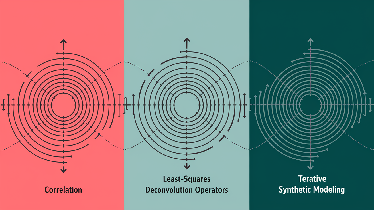
Cross‑correlation isn’t the only way to measure radial velocities. Least‑squares deconvolution (LSD) builds an average line profile by deconvolving the observed spectrum with a line mask, effectively reversing the convolution of individual line profiles with instrumental response. LSD produces a high signal‑to‑noise mean line profile similar to the CCF but can better preserve asymmetries and time‑variable line shapes, making it useful for detecting magnetic fields and stellar activity signatures. LSD requires careful normalization and is more sensitive to mask errors than standard cross‑correlation, though.
Forward modeling fits synthetic spectra directly to observed data, adjusting stellar parameters (effective temperature, surface gravity, metallicity) and radial velocity at the same time. This approach accounts for line blending, continuum shape, and instrumental profile self‑consistently, and can hit sub‑m/s precision when stellar models are accurate. Forward modeling is computationally expensive (each fit may take minutes) but avoids some biases from template mismatch. It’s especially valuable for stars with complex spectra, rapid rotation, or chemical peculiarities where a single template or mask falls short.
Template‑free methods, like those based on principal component analysis or data‑driven models, learn spectral variability directly from a time series of observations. These techniques can separate the velocity‑induced Doppler shift from activity‑driven line‑shape changes without assuming a specific template. They’re still under active development and show promise for disentangling planets from stellar noise, but they need large datasets and careful validation. For most current surveys, cross‑correlation remains the workhorse. It’s fast, well understood, and performs reliably across a wide range of stellar types and signal strengths.
Final Words
You saw how the CCF turns many spectral lines into a single, sharper signal, how templates and masks are made, and how instruments and calibration reach sub-m/s precision. We also covered the math that finds the velocity lag and the noise that can fool us.
That chain of observation, correlation, peak fitting, and careful calibration lets us extract planet signals from tiny Doppler shifts. It’s patient work and good engineering.
For anyone using cross-correlation techniques for detecting exoplanets via radial velocity, the payoff is clearer detections and better mass estimates. Keep watching spectra and you’ll help spot new worlds.
FAQ
Q: What is the cross-correlation function (CCF) and how does it detect Doppler shifts?
A: The cross-correlation function (CCF) measures similarity between an observed stellar spectrum and a reference; Doppler shifts show up as shifts in the CCF peak, revealing the star’s line-of-sight velocity.
Q: Why are CCFs central to radial-velocity exoplanet searches?
A: CCFs are central because they combine many spectral lines into one composite profile, boosting signal-to-noise and letting tiny, periodic velocity shifts from orbiting planets be measured more precisely.
Q: How do templates and binary masks work when building a CCF?
A: Templates or binary masks encode ideal line positions; cross-correlating the observed spectrum with them highlights matching line patterns and isolates velocity shifts, while masks pick which lines contribute to the signal.
Q: What are the main processing steps to construct a reliable CCF?
A: The main steps are selecting a template or mask, preprocessing the spectrum (normalize, remove instrument effects), shifting the template across a velocity grid, computing the correlation, and fitting the CCF peak for velocity.
Q: How is the CCF computed mathematically and how is radial velocity extracted?
A: The CCF is computed by sliding the template over velocity lags and integrating similarity across wavelengths; the peak’s velocity gives the radial velocity, often refined by fitting a Gaussian or similar profile.
Q: What instruments and calibration methods enable sub‑meter‑per‑second CCF precision?
A: High-precision CCF analysis needs a stable, high-resolution spectrograph, precise wavelength calibration with emission lamps or a laser frequency comb, and linear, temperature-controlled detectors to limit drift.
Q: What noise sources limit CCF‑based radial-velocity measurements and how do they affect the CCF?
A: Stellar activity, granulation, photon noise, and spectrograph drift distort the CCF shape or shift its peak, biasing velocities and setting practical precision limits that require mitigation and careful monitoring.
Q: How are CCF-derived velocities used to detect exoplanets and estimate their masses?
A: Periodic shifts in the CCF peak trace the star’s reflex motion; measuring the period and semi-amplitude yields orbital period and semi-amplitude, which combine to give the planet’s minimum mass, m sin i.
Q: How does the CCF method compare to alternatives like forward modeling or least-squares deconvolution?
A: The CCF method is efficient and robust, compressing many lines into one profile, while forward modeling and line-by-line approaches can offer improved precision for complex spectra at higher computational cost.